Introduction
Part III provides the foundational knowledge and practical tools needed to model and use ontologies in digital engineering contexts. It explains how ontologies serve as precise, machine-readable frameworks for representing domain knowledge, enabling seamless data integration and automated reasoning across complex engineering systems.
| Ontologies are not just data dictionaries—they are formal models that capture logical relationships and constraints within a domain, allowing machines to understand and reason about data in context. |
Overview
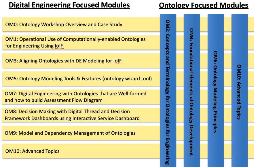
Part III covers the essential principles and tools for developing, managing, and applying ontologies in digital engineering. It serves as the practical guide for readers who need to implement ontology-based solutions for interoperability and knowledge representation. Key topics include:
-
Ontology fundamentals: Core concepts and principles of ontology development
-
Ontology tools: Protégé and other tools for ontology authoring
-
Top-level ontologies: BFO and its role in structured knowledge representation
-
Domain ontologies: CCO and how to build upon them
-
Ontology alignment: Techniques for integrating ontologies with engineering models
Part III bridges the gap between theoretical understanding and practical implementation, providing readers with the skills to create and use ontologies that support interoperability across engineering domains.
| The key insight: Ontologies enable machines to understand the meaning of data, not just the data itself, which is essential for automated reasoning and cross-domain integration in digital engineering. |
Position in Knowledge Hierarchy
Broader concepts: - Handbook on Digital Engineering with Ontologies (contains)
Narrower concepts: - Ontology (is-a) - BFO (is-a) - CCO (is-a) - Protégé (is-a)
Details
Ontology Fundamentals
An ontology is a formal representation of knowledge within a specific domain, defined by:
-
Classes: Categories of entities (e.g., "Catapult", "SafetyMechanism")
-
Properties: Relationships between entities (e.g., "hasPart", "isActivatedBy")
-
Axioms: Logical constraints (e.g., "a catapult must have a launch arm")
| Ontologies differ from simple data dictionaries because they include logical constraints and relationships that allow for automated reasoning and validation. |
The table below summarizes key ontology concepts and their engineering applications:
Concept |
Engineering Application |
Class |
Representing system components (e.g., "PropulsionSystem") |
Object Property |
Describing relationships between components (e.g., "isPartOf") |
Data Property |
Storing measurable attributes (e.g., "mass", "velocity") |
Axiom |
Enforcing constraints (e.g., "a missile must have one warhead") |
Instance |
Specific realization of a class (e.g., "M1A1Tank") |
Ontology Development Principles
When developing ontologies for digital engineering, adhere to these fundamental principles:
|
| Avoid creating ontologies that are "too big" or "too general." Focus on the specific needs of your engineering context rather than attempting to model "everything." |
BFO: The Foundation for Engineering Ontologies
BFO (Basic Formal Ontology) is a top-level ontology that provides a philosophical foundation for representing entities and their relationships. It’s the recommended TLO for engineering ontologies because:
-
It provides a consistent framework for modeling entities across domains
-
It follows a rigorous philosophical foundation that avoids common pitfalls in ontology development
-
It’s widely adopted in the engineering community for interoperability
BFO’s key components include: - Continuants: Entities that persist through time (e.g., physical objects) - Occurrents: Entities that happen over time (e.g., processes) - Dependents: Entities that depend on other entities (e.g., attributes)
| BFO’s philosophical underpinnings ensure that ontologies built on it are logically consistent and interoperable with other BFO-conformant ontologies. |
CCO: The Common Core Ontologies
CCO (Common Core Ontologies) is a collection of mid-level ontologies that provide reusable building blocks for domain-specific ontologies. It includes:
-
Common Core Artifact Ontology: For representing physical objects and their properties
-
Common Core Function Ontology: For describing capabilities and functions
-
Common Core Process Ontology: For modeling workflows and processes
The CCO is designed to be imported into domain-specific ontologies, providing standardized terms for common engineering concepts.
| When importing CCO, ensure you preserve the original IRIs (Internationalized Resource Identifiers) to maintain interoperability with other ontologies. |
Protégé: The Ontology Development Environment
Protégé is a free, open-source ontology editor that provides a graphical interface for creating and managing ontologies in OWL format. It’s the primary tool recommended for ontology development in the handbook.
| Download Protégé from https://protegewiki.stanford.edu/wiki/Main_Page |
Protégé Interface Overview
Protégé is organized into Views and Tabs, with the most important being:
Tab |
Function |
Active Ontology |
View and edit ontology metadata |
Classes |
Create and manage classes |
Individuals |
Define specific instances of classes |
DL Query |
Run logical queries using Manchester OWL syntax |
SWRL Tab |
Create rules for automated reasoning |
Basic Ontology Development in Protégé
Here’s a step-by-step guide to creating a simple ontology for a catapult system:
|
| Use clear, descriptive names for classes and properties (e.g., "SafetyMechanism" instead of "SM") to ensure readability and maintainability. |
Ontology Alignment with SysML Models
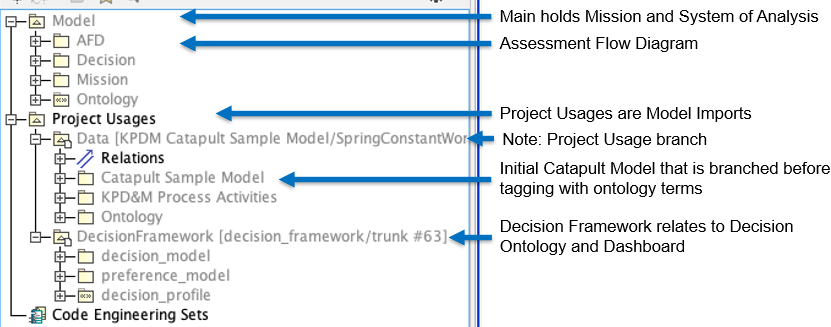
The handbook emphasizes aligning ontologies with SysML models to enable interoperability. This involves:
-
Tagging model elements with stereotypes: Using SysML stereotypes to link model elements to ontology classes
-
Creating an Assessment Flow Diagram (AFD): Defining the relationships between system elements and analysis models
-
Using the AFD to configure IoIF: The AFD provides the structure for data flow between models
| The key to successful alignment is using consistent naming conventions across both the ontology and SysML model. |
| Refer to Section 5 of "Semantic Web for the Working Ontologist" for detailed guidance on SysML-OWL alignment. |
Practical applications and examples
Ontology Alignment Example: Catapult Safety Mechanism
Let’s extend the catapult example from the handbook to include a safety mechanism. This demonstrates how to align an ontology with a SysML model.
|
| The following code snippet demonstrates how to query the ontology for safety mechanisms using SPARQL: |
PREFIX cat: <http://example.org/catapult#>
SELECT ?safetyMechanism
WHERE {
  ?safetyMechanism a cat:SafetyMechanism .
}
Related wiki pages
References
Knowledge Graph
Visualize the relationships between Part III and related concepts
Associated Diagrams